


Elevated Sprocket Dozer Maintenance Guide for Long-Term Operation
 Aug. 31, 2026
Keeping an Elevated Sprocket Dozer productive for years requires more than changing engine oil on schedule. In this Elevated Sprocket Dozer Maintenance Guide for Long-Term Operation, I explain a practical maintenance system for HBXG machines—from daily walk-around inspections and track adjustment to final-drive protection, undercarriage measurement, contamination control, and service documentation. Whether you are a first-time owner or an experienced fleet manager, follow the process in stages: confirm the machine’s service manual, inspect before operation, lubricate with the correct specification, measure wear before failure, repair root causes, and record every intervention. This approach helps reduce unplanned downtime while protecting the elevated sprocket, track chain, rollers, idlers, final drives, hydraulic system, and powertrain.
!
Why HBXG Elevated Sprocket Dozer Maintenance Matters
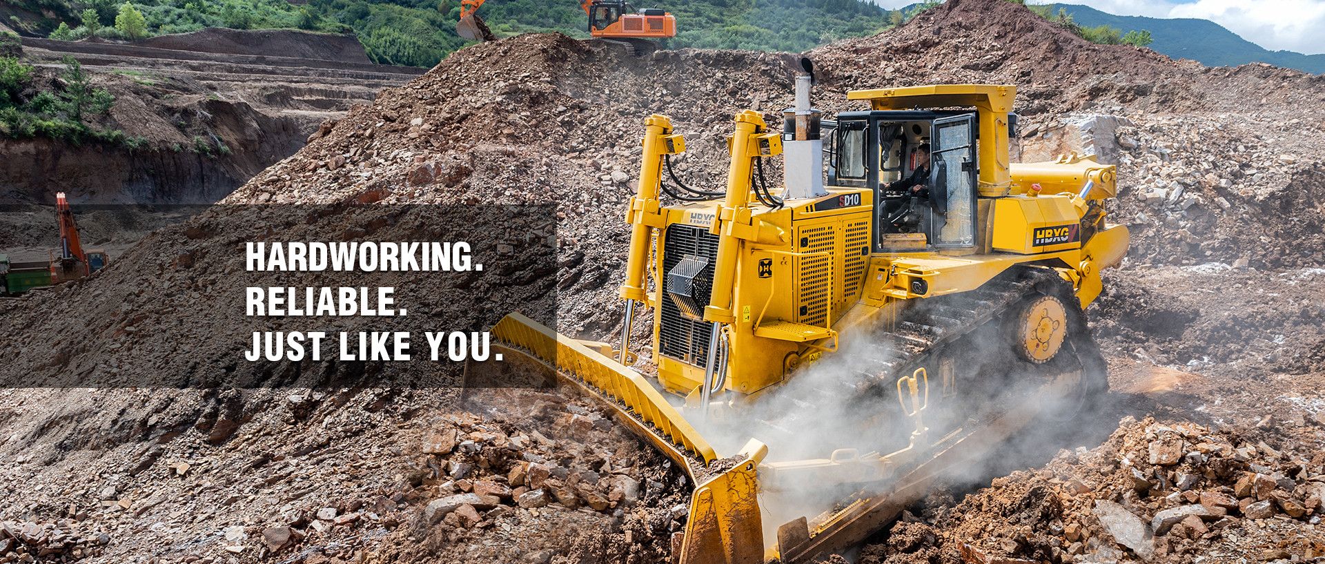
An HBXG Elevated Sprocket Dozer separates the drive sprocket and final drive from the lower track frame. This configuration helps protect the powertrain from ground impact, but it also places greater importance on:
- Track chain alignment
- Carrier roller and lower roller condition
- Final-drive oil quality
- Track tension
- Sprocket and bushing engagement
- Frame, mounting, and pivot-point inspection
The undercarriage may represent a significant share of operating cost. A small issue, such as incorrect track sag, can accelerate bushing wear, increase rolling resistance, and overload the final drive. For this reason, we recommend treating maintenance as a controlled reliability program rather than an emergency repair activity.
The exact service intervals must always follow the HBXG operation and maintenance manual, ambient conditions, and attachment configuration. Severe applications—including rock excavation, demolition, abrasive sand, forestry, and continuous dozing on slopes—normally require shorter inspection intervals.
Stage One: Establish a Maintenance Baseline
Before the first operating shift, I recommend creating a machine baseline. This makes later changes easier to identify and prevents technicians from relying only on visual judgment.
Record the machine condition
Document the following information:
- Machine model, serial number, and operating hours
- Engine, transmission, hydraulic, and final-drive oil specifications
- Track shoe width, grouser profile, and chain configuration
- Current track sag on both sides
- Sprocket, bushing, roller, and idler condition
- Hydraulic hose routing and cylinder leakage
- Battery voltage and charging-system condition
- Existing cracks, weld repairs, or abnormal noise
Use calibrated tools wherever possible. For precision checks, a digital caliper or ultrasonic thickness gauge with resolution to 0.01 mm can improve repeatability. Measurement accuracy is only useful when the same reference points are used each time, so mark inspection locations and record whether measurements were taken on the left or right side.
Prepare a service file
A simple service file should contain:
- Daily inspection sheets
- Lubricant and filter records
- Undercarriage measurement reports
- Fault-code printouts
- Photographs of abnormal wear
- Parts replacement dates
- Technician name and operating hours
For fleet operations, a digital maintenance platform can issue alerts at 50-hour, 250-hour, 500-hour, and annual intervals. These intervals are examples only; the HBXG manual remains the controlling document.
Stage Two: Complete the Daily Walk-Around
A daily walk-around is the first defense against expensive failure. Perform it with the engine stopped, attachments lowered, parking brake engaged, and the machine isolated according to the site’s lockout/tagout procedure.
Inspect the elevated sprocket and final-drive area
Look for:
- Oil leakage around final-drive seals
- Damaged guards or loose mounting bolts
- Cracks around the elevated sprocket support
- Missing fasteners
- Abnormal grease or mud accumulation
- Metal particles near drain plugs or magnetic inspection points
A final-drive leak should not be dismissed as a minor seepage. Low oil level can cause gear and bearing damage, while contaminated oil can produce abrasive wear. If oil appears milky, water contamination is likely. If it contains bright metallic particles, stop operation and arrange a detailed inspection.
Inspect the undercarriage
Check both sides for:
- Loose or damaged track shoes
- Missing master pin retainers
- Broken or stretched track links
- Uneven bushing wear
- Cracked roller flanges
- Idler face damage
- Excessive mud packing
- Track frame misalignment
Track shoes should be tightened to the torque specified by HBXG. Do not estimate torque with a standard wrench. Under-torqued bolts may loosen, while over-torqued bolts can stretch or fail.
Check fluid levels and visible leaks
Inspect engine oil, coolant, hydraulic oil, transmission oil, and final-drive oil using the correct procedure and temperature condition. A fluid level can appear incorrect if the machine is parked on uneven ground or checked immediately after operation.
Also inspect:
- Hydraulic hose abrasion
- Cylinder rod pitting
- Radiator and oil cooler blockage
- Fuel-system leakage
- Fan-belt condition
- Battery terminals
- Air-intake restriction indicator
Clean debris with controlled air or low-pressure water. Avoid forcing water into electrical connectors, seals, breathers, and bearings.
Stage Three: Manage Track Tension Correctly
Incorrect track tension is one of the most common causes of accelerated undercarriage wear. Track adjustment must be performed on level ground, with the machine configured exactly as described in the HBXG service documentation.
Use the correct measurement method
Track sag can vary according to:
- Shoe width
- Ground conditions
- Track design
- Carrier roller arrangement
- Machine operating temperature
- Presence of packed material
Do not copy a universal sag value from another dozer model. Measure at the specified span and reference point. If the track is too tight, the machine may experience increased roller and bushing load. If it is too loose, derailment risk and sprocket disengagement increase.
A practical procedure is:
- Park on a firm, level surface.
- Remove packed soil from the undercarriage.
- Move the machine forward and stop without applying unnecessary reverse tension.
- Measure track sag using a straightedge, tape, or approved HBXG gauge method.
- Compare the measurement with the manual.
- Adjust through the recoil spring and grease-cylinder system only as instructed.
- Recheck after a short test movement.
Never stand directly in front of a track adjuster or attempt to remove a grease fitting under pressure. Hydraulic grease pressure can cause serious injury. Release pressure using the manufacturer’s safe procedure and wear eye and face protection.
Stage Four: Lubricate and Control Contamination
Lubrication is not simply adding grease until it becomes visible. The correct lubricant, cleanliness, quantity, and interval all matter.
Use the correct lubricant
Confirm the required viscosity and performance class for:
- Engine oil
- Hydraulic fluid
- Gear oil
- Grease
- Coolant
- Fuel-system additives
For gear and final-drive oil, consider the manufacturer’s required API or equivalent performance level. For grease, verify the NLGI grade and compatibility with seals and bushings. Mixing incompatible grease types can cause separation, hardening, or loss of film strength.
Follow contamination-control practices
When servicing an HBXG Elevated Sprocket Dozer:
- Clean filler caps before opening
- Use dedicated, labeled containers
- Keep new oil sealed until use
- Replace damaged breathers
- Wipe dipsticks before and after measurement
- Use clean transfer pumps
- Cap hoses and fittings immediately
- Dispose of used fluids according to local regulations
For high-value machines, periodic oil analysis is a useful predictive-maintenance tool. A laboratory can identify viscosity change, oxidation, water, silicon, iron, copper, and other wear metals. Set alarm limits with the equipment manufacturer or qualified laboratory rather than relying on generic values.
Stage Five: Inspect the Undercarriage by Measurement
Visual inspection identifies obvious damage, but measurement identifies wear before a breakdown. We recommend taking undercarriage readings at consistent operating-hour intervals and after severe applications.
Measure critical wear components
Depending on the HBXG model and track system, inspect:
- Track-link height
- Bushing outside diameter
- Pin and bushing wear
- Sprocket tooth profile
- Roller tread diameter
- Roller flange thickness
- Idler tread diameter
- Track shoe grouser height
- Track-frame alignment
Record the percentage of wear where the manufacturer provides a wear chart. When a component approaches its service limit, plan a controlled replacement rather than waiting for a broken chain or failed roller.
Precision tools should be calibrated. For dimensional inspection, maintain calibration records and use a repeatability target appropriate to the component. A 0.01 mm display resolution is useful for comparison, but it does not automatically mean the measurement has 0.01 mm accuracy.
Interpret wear patterns
| Wear pattern | Likely cause | Recommended action |
|---|---|---|
| Fast inner-flange wear | Misalignment or side loading | Check track frame, rollers, and operating technique |
| Sprocket tooth hooking | Extended bushing wear or incorrect engagement | Measure sprocket and chain; plan matched repair |
| Uneven shoe wear | Poor tension or abrasive ground | Correct tension and review work route |
| Roller leakage | Seal damage or overheating | Replace or rebuild according to service limits |
| Repeated track derailment | Loose track, damaged guide, or alignment problem | Stop operation and inspect the complete track system |
Replacing only one worn component may produce poor engagement. For example, a severely worn sprocket paired with a new chain can create rapid contact stress. A qualified technician should determine whether sprocket, chain, bushings, pins, rollers, and idlers require individual or matched replacement.
Stage Six: Protect the Powertrain and Hydraulic System
The elevated sprocket design helps isolate the final drive, but the powertrain still depends on clean fluids, correct cooling, and proper operating technique.
Engine and cooling system
At scheduled intervals:
- Inspect coolant concentration and freeze protection
- Clean radiator and oil-cooler cores
- Check fan, belt, and tensioner condition
- Replace fuel and oil filters using approved parts
- Inspect the air filter restriction indicator
- Look for coolant stains around hoses and water-pump areas
Do not use high-pressure water directly against cooling fins. Bent fins reduce airflow and may require professional cleaning or straightening.
Hydraulic system
Inspect hydraulic cylinders, pumps, valves, and hoses for:
- External leakage
- Hose blistering
- Abrasion against the frame
- Rod scoring
- Slow attachment movement
- Excessive hydraulic noise
- Unusual oil temperature
Hydraulic cleanliness is commonly managed using ISO 4406 particle-count reporting. Where applicable, request a cleanliness target from the machine or component supplier. Filter replacement should follow the service schedule and contamination findings—not only appearance.
Stage Seven: Apply Safe Operating Practices
Maintenance cannot compensate for damaging operating habits. I have found that operator training often produces the fastest improvement in undercarriage life.
Train operators to:
- Avoid high-speed travel over rough ground
- Minimize counter-rotation on abrasive surfaces
- Keep the blade load within rated capacity
- Avoid prolonged track spinning
- Use gradual directional changes
- Remove packed material during shift breaks
- Travel with the elevated sprocket and final drive protected from direct impact
- Report abnormal vibration, noise, heat, or oil leakage immediately
On slopes, use the operating orientation and travel direction recommended by HBXG. Repeated side loading can accelerate flange wear and increase the risk of track derailment.
A Practical Service Schedule
| Interval | Main tasks |
|---|---|
| Every shift | Walk-around, fluid check, leakage inspection, track and shoe inspection |
| Weekly or approximately 50 hours | Grease specified points, clean undercarriage, inspect fasteners and guards |
| Approximately 250 hours | Replace or inspect scheduled filters and fluids; check track adjustment and battery system |
| Approximately 500 hours | Perform detailed undercarriage measurement and oil-condition review |
| Annually | Inspect structural welds, final drives, hydraulic system, cooling system, and safety equipment |
These intervals are a planning framework, not a substitute for the HBXG maintenance manual. In severe duty, shorten the intervals and increase oil sampling frequency.
Example: Reducing Unplanned Downtime
In one fleet-maintenance program involving an elevated-sprocket crawler dozer working in abrasive aggregate, the operator initially adjusted tracks only after derailment occurred. The maintenance team then introduced three controls:
- Daily track-sag records
- Undercarriage measurements every 250 operating hours
- A mandatory cleaning and inspection period at the end of each shift
Within the next service cycle, the fleet identified sprocket hooking and uneven roller wear before component failure. The repair was scheduled during planned downtime instead of during production. The result was better parts planning, fewer emergency callouts, and more consistent machine availability.
The lesson is not that every machine will achieve the same result. Rather, the case demonstrates the value of measurement, documented thresholds, and early intervention.
Tools and Resources for an HBXG Maintenance Program
Keep the following resources available:
- HBXG operation and maintenance manual
- Service and parts manuals
- Calibrated torque wrench
- Digital caliper and wear gauges
- Track-sag measuring tool
- Grease gun with correct lubricant identification
- Oil-sampling bottles
- Flashlight and inspection mirror
- Infrared thermometer
- Hydraulic pressure test equipment for qualified technicians
- Cleaning tools and spill-control materials
- Digital maintenance log with photographs
For dimensional quality control, follow documented calibration procedures. Where material or weld quality is being evaluated during repair, qualified inspectors may reference applicable ASTM material requirements, DIN dimensional specifications, and approved welding procedures. Visual weld inspection can be supported by standards such as ISO 17637, while non-destructive testing should be performed by trained personnel using the appropriate method.
Common Problems and Practical Solutions
Track adjustment does not hold
Possible causes include a leaking recoil adjuster, damaged seal, trapped contamination, or incorrect adjustment procedure. Clean the area, verify grease-cylinder condition, and have the system pressure-tested by qualified personnel. Do not repeatedly add grease without finding the cause.
Final-drive oil becomes contaminated
Inspect breathers, seals, drain-plug condition, and water entry points. Take an oil sample before draining when possible. If metal content is elevated, inspect bearings and gears rather than simply refilling with new oil.
The machine pulls to one side
Check track tension on both sides, shoe condition, roller resistance, brake or steering-system performance, and frame alignment. Unequal track resistance can indicate an undercarriage or powertrain issue.
Components wear too quickly after replacement
Confirm that replacement parts match the exact HBXG model and configuration. Check sprocket-to-chain compatibility, installation dimensions, torque, alignment, lubrication, and operating conditions. A new component installed beside a severely worn mating component may fail prematurely.
Final Checklist for Long-Term HBXG Dozer Operation
Before returning the machine to production, verify:
- Track sag matches the HBXG specification
- No final-drive or hydraulic leaks are present
- Sprocket and chain engagement is acceptable
- Roller and idler seals are intact
- Track-shoe bolts are correctly torqued
- Engine, hydraulic, transmission, and gear oils are at the correct levels
- Cooling cores are clean
- Grease points have been serviced
- Safety guards and access panels are secure
- All findings are recorded with operating hours and photographs
A disciplined Elevated Sprocket Dozer Maintenance Guide for Long-Term Operation should always combine daily observation, scheduled lubrication, dimensional measurement, contamination control, operator training, and planned component replacement. By applying these practices to an HBXG Elevated Sprocket Dozer, we can identify wear earlier, protect the elevated final drive and undercarriage, improve maintenance planning, and support reliable operation over the machine’s service life.


